It’s been a while since I wrote a post. Last weekend was a typical bridge workday, when the company usually gives an option to work on something mind blowing and fun.
Previous Hackathon
The last such occasion was 17th of May, when I was working on setting up a digital twin of a robotic arm in Meta Quest, while the others were building the robotic arm and making it function as intended.
Anyway, when that hackathon was over, the organizers pitched that the next hackathon will be in October, and ideas that combine AI and Robotics are more than welcome. At that time I was really into drawing, and my idea started to grow that I want to make an AI driven CNC pen plotter.
What is a CNC Pen Plotter?
A CNC (Computer Numerical Control) pen plotter is a machine that automatically draws images by moving a pen based on computer instructions called GCode. Think of it as a robotic arm that can precisely recreate digital drawings on paper.
Idea for this Hackathon
My goal was to create a web application that drives the whole process of creating art and putting it onto paper.

Processing steps
I split the process into seemingly logical parts:
- Select image Source
- Adjust Raster image to a new Raster image
- Transform Raster image to SVG (Scalable Vector Graphics)
- Run
svgooptimizer optionally - Convert SVG to GCode (machine control instructions)
- Optionally Preview GCode in the app before sending
- Send GCode to the plotter
I chose CNC.js as my GCode sender and wrote my UI code as a custom TypeScript widget.
I bought an entry level CNC so that I don’t have to go deep too soon and drown in the possibilities of designing my own structure and fine tune it to perfection.
Tech Stack Overview
The system has three main components:
- Frontend: React with TypeScript
- Backend: FastAPI with Celery workers for async processing
- Hardware Control: FluidNC firmware on MKS DLC32 v2 controller
- AI Tools: ComfyUI for image enhancement, Ollama, MCP for agents
There are also minor technical experiments that are part of it but not essential.
Original plan
My original plan for this hackathon was a workflow to:
- Take a picture of a person in front of the camera
- Enhance the image with AI to add silly face expressions
- Generate line drawing sketches with recognizable face
- Draw them to the person as if they’re at a photobooth
Technically my app is capable of doing it, but I had lower level problems before I could achieve this workflow.

Select image

Enhance image

Create line drawing

Preview result
Technical Challenges with the Photobooth
While I was developing, I found some issues that made this challenging.
AI Image enhancements
First of all, I did not want to pay for hobby development to an AI image enhancement service, so I needed to find a local engine. Luckily I found ComfyUI fairly quickly and fell in love with its ease of use.
After that I needed to find pretrained models that work well. I found models for drawing realistic faces and models to actually do the sketches from the face.
Model Biases
When I got to the point of testing out the facial expression modifications, I was a bit shocked when the test image of a man smiled back at me as a woman. Apparently these models were trained on datasets that associated certain facial expressions with specific genders. The terms I used in my prompts like “smiling” or “surprised” triggered these unintended transformations.
Through prompt engineering (carefully crafting the text instructions given to the AI), I added gender specific terms like “masculine smile” or “bearded person looking happy” to the mix, and these biases went away. To prevent malfunction and surprises, I added an explicit selector to choose whether to add masculine or feminine terms to the prompt.

Original Image

First trial of my prompts
Line sketch
I figured out ways to create a sketch from the image. I found edge detection
working really well. I also found a model that I could use through ComfyUI
to do the heavy lifting for me. The most challenging part was to clean up the
rubbish that shall not be in the image and preferably do it automatically.

Line sketch generation with artifacts
Recognizable face
The most challenging part was to actually make it look like a face.
I haven’t yet solved this issue. I have some heuristics to detect the background and remove it, try to detect the face and make its features stronger, but it cannot handle light differences and accessories well, so I parked this for a while.

Man with glasses
Changing the Plan
Due to these problematic parts, I figured if I was not able to fix it in my limited free time over weeks, I won’t be able to solve them in a single day. Rather than force the photobooth workflow, I decided to change direction and focus on solving the hardware challenges first, while still adding new features that seemed fun before the big day arrives.
While I was developing the app, my order arrived with the parts, so I spent a day assembling it and trying it out. To my surprise, this particular device only worked with its proprietary software.
As I learned, the internet is filled with generative art and CNC enthusiasts, so I found ideas on how to circumvent this problem. I ordered new parts in a hurry and decided that I’ll spend the hackathon day to assemble the new controller.
Hackathon day

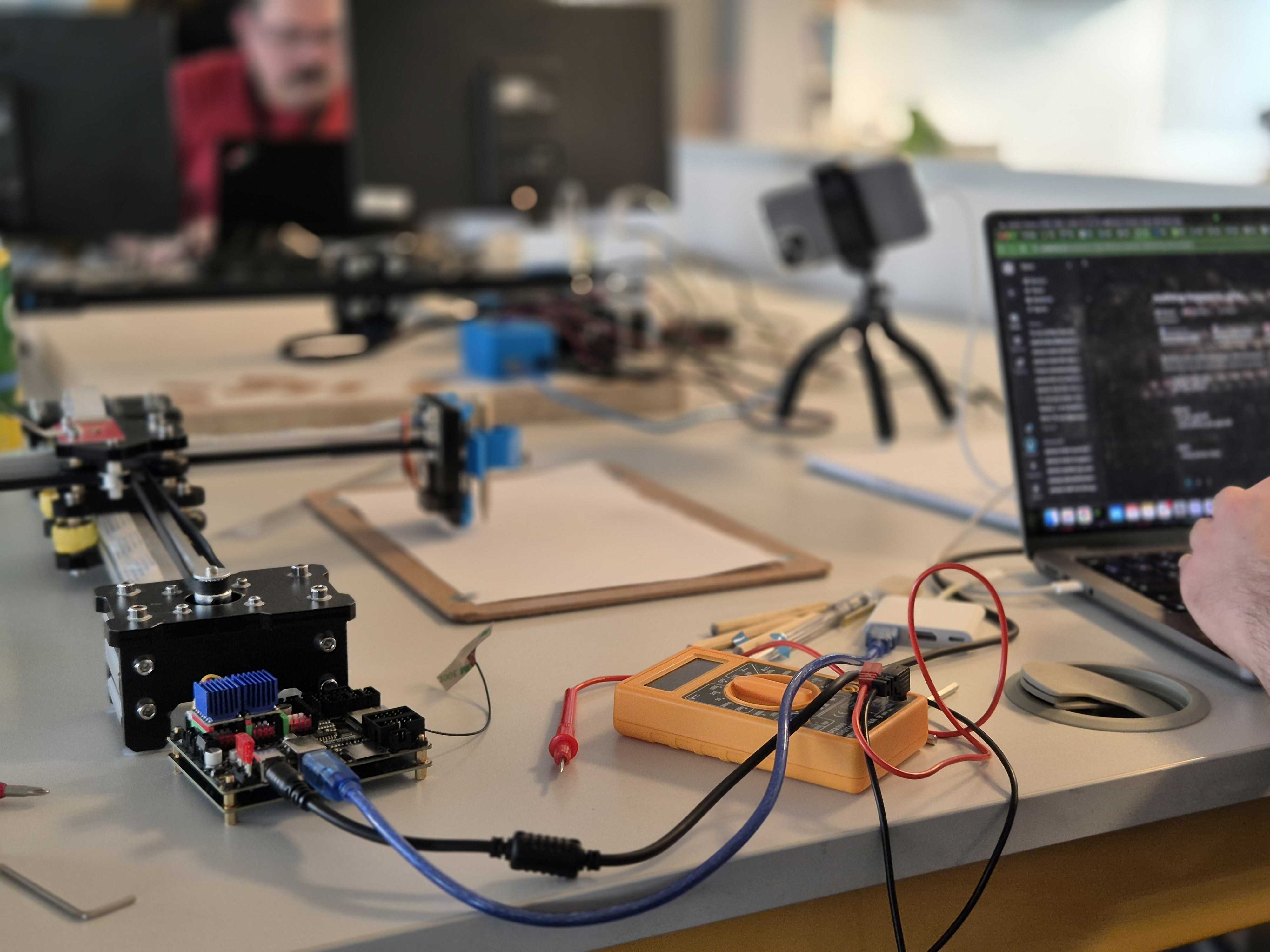
Our desk
Before the event, during registration I pitched my idea and marked that I don’t have a team, so some colleagues joined to my efforts. One of them helped me with a 3D printed case (thank you Zoli!) and another brought in his actual working plotter (thanks Dénes!).
Hardware dev
Things started out slowly. I spent the morning wrapping my head around the different options I had.
My goal was to use my software instead of a windows-only app and make the basic functionality live, as in move the X and Y axis motors and lift the pen with a servo.
I bought an MKS DLC32 v2 with a TFT screen. Soon I realized that I cannot
simply make the pen lift function work with the stock firmware, so I decided
to switch to FluidNC and shed a tear of
why I did not choose Arduino with a CNC
shield.
Since FluidNC does not support displays, and this display was designed
specifically for this board, I put it away as well.
I started by connecting the motors and the stepper drivers. Another reason I
regretted my choice retrospectively is that the board doesn’t support UART
(Universal Asynchronous Receiver-Transmitter), a communication protocol that
would let me configure the stepper motor drivers through software. Instead, I
needed to manually configure them using a multimeter to set the voltage
reference (Vref) for my TMC2208 stepper drivers. After I set it to a
seemingly safe value, I was extremely satisfied when the motors started to
move smoothly.

Proud moment: My first drawn line
Digital Fingerprint
Then I moved on to the next step to make the pen lift functionality work. That’s where I hit a wall for the day. I did not find clear reference on how to make it work, and I did not bring dupont cables to play with the pins (sidenote: yesterday night I figured out that I can use pin 25 as PWM to control the Z axis 🎉).
Since the hardware wasn’t cooperating, I shifted focus to a creative feature Dénes was working on.
Dénes had an idea to make a wordplay on digital fingerprints and someone’s identifiability by their commits in a GitHub repository. The concept was to fetch someone’s commit history and merge the data into a seed for a random noise generator to create curl noise that can be transformed into an oval fingerprint like structure. Each person’s commit pattern would generate a unique visual fingerprint.
After my failure, I joined in to add his implementation to my site. The
challenge was that my site only supports image processing methods written in
Python, but he did it in p5.js, so I needed to add a new image generator
method to the UI that takes a p5.js code, runs it and takes the image,
and works with it to generate the image and the drawing.

Digital fingerprint Settings

Digital fingerprint Image

Digital fingerprint GCode Preview

Digital fingerprint Result
Day closure
I presented my app and the digital fingerprint idea with the drawing that we made. People really liked it. They came to me afterwards to ask about specific parts, and they really liked that we had an actual machine that they could touch.
I did a quick demo to generate GCode and made it into preview stage, but we could not set the plotter up for a live demo this time as the mechanical switches started to malfunction by the end of the day.
Beyond the Hackathon
As I mentioned, I spent months on this project leading up to the hackathon, so I added many features I wanted to explore. Here are some of the most challenging or fun parts:
Core Features
Image Processing & Generation
- Generate text that looks like handwriting using single line fonts from TTF and Hershey vector fonts, adding jitter and making sure the SVG is not too complex
- Generate QR codes
- Cache generated images in Redis if I generate them with the same settings
- Have my own custom GCode preview instance
- Run user written Python scripts in the backend with safety measures embedded, with templates like zentangle drawer, postcard writer according to Hungarian letter format, weather info through API. These scripts are written in Monaco Editor (the same editor that powers VSCode)
SVG to GCode Pipeline
- Add a configuration encoder/decoder to SVG and GCode files to ease reproducibility
- Handle GCode tool change with multiple colors and stroke width
- Write my own passthrough GRBL simulator
Infrastructure & Development Tools
Backend Architecture
- Send jobs to
Celeryworkers (distributed task queue for async processing) - Write a log-collector service and inspect logs in
Kibana - Write a separate server in
Rustthat handles image processing - Try
Protobuf(Protocol Buffers) for efficient backend to backend communication
AI Integration
- Use AI agents that use MCP server (Model Context Protocol)
- Add a
Streamlitapp and connect it toollamato call my FastAPI backend - Host a Jupyter server to prototype faster
- Blazeface Face detection to crop the user’s face from the camera stream
Development Environment
- Read from macOS camera stream, and forward it to the backend to stream to the user
- Use
httpdto share files to have a retro feeling with Apache FTP servers to speed up example sharing on the big day - GCode sender via WebSocket to
FluidNCin case I cannot make it work withCNC.js - I wrote the presentation in revealjs, and hosted it with my CLI tool
In these few months I was able to practice AI Driven Development and experience first hand how certain models evolved. I used it mostly when a feature seemed fun to showcase, but I did not have the mental capacity to dive deeper into its background. Later I sat down and fine tuned when I had better ideas.
SVG to GCode Generation
Initially I thought it’s a solved problem to convert SVG to machine code. I
found tools that aim to do this, but they did not fit my extensibility needs,
so I ended up coding it from scratch. I do not plan to support every CSS
feature of SVGs, but I support the SVG elements like circle, ellipse,
rect, line, path, polyline, polygon.
Tool change
I added support for handling color and stroke widths by grouping them into
tools that are supported by GCode, so basically if a user wants to use 2
colors, CNC.js will stop halfway and ask the user to change the tool
manually, and then confirm that the tool change happened, and when they click
the button the drawing continues.
Path Optimization
The trickiest part is adding optimizations to minimize pen travel time. Since finding the optimal path is mathematically complex (an NP-complete problem similar to the famous Travelling Salesman problem), I decided to let others handle the heavy lifting and chose OR-Tools by Google. I added heuristic scoring points to each path segment for the optimizer to work with.
Approaching the Shapes
Another challenging piece was to determine which direction the plotter should approach each shape. At first, each of my shapes were drawn from the bottom left corner. Imagine you have 4 rectangles in a 2 by 2 grid. The optimal drawing order is definitely not the one where you travel through the whole shape just to arrive to that specific corner on the bottom left.
So I added dynamic code generation after the optimization. When I assemble the final machine code, my module tracks the current location of the pen, takes the next segment and calculates the Euclidean distance to all possible entry points. It chooses the entry point closest to the pen and draws the shape as if it was originally started from that point. For circles, I find the closest point on the circumference and draw 2 semicircles. For paths and polylines, I need to check whether it’s a closed shape or I only have 2 entry points.
AI MCP server
The internet is full of AI, MCP servers and Agents. I haven’t jumped on the hype train yet because I do not have a personal subscription for any of the big model providers, and any time I tried to run agentic code editing locally my machine basically froze.
I really liked the idea to have a chat app where I can ask an LLM to generate some text for me and have it use an MCP server (Model Context Protocol, a standard that lets AI models call external tools and services) to actually ask another service to do the work.

Streamlit coordinated Poem writing through my API via an MCP using agent
I found a local model for ollama that supports agentic behaviour and I was
able to set it up: qwen3:8b. I chose FastMCP to spare many hours of
headaches of low-level MCP implementation and focus on the fun parts to wire
things together.
I added 2 tools:
- One that generates the SVG using the handwriting image generator
- Another one that generates machine code from the last SVG and lets the user download or preview the image

AI handwriting result GCode preview
Docker Serial connection
As I learned, in Mac Docker cannot make serial connections with the USB devices that are connected to the machine, so I needed to figure out a way how to sneak this info through.
My solution is to have a task running alongside my docker-compose script
that runs ser2net and forward it to a
TCP port. Then have a service inside Docker that runs a
socat command that maps it into a
virtual /dev device. To all my surprise, it works pretty well.
I haven’t yet found how CNC.js supports streaming GCode over the network,
but in theory this way could work. I just need to rewire socat to the
network address of the CNC instead of ser2net.
Improvement possibilities
As I mentioned, I have a bunch of ideas how to enhance this project.
One of them is to have a scheduled task runner, so that I can spice up my life with a morning note that is read from my calendar and has my schedule for the day on paper along with the expected weather and the quote of the day. It would promote being analog and get away from my phone in the mornings.
Closing words
I really enjoyed this hackathon. It was challenging, action packed and full of surprises. My adrenaline level was peaking due to the time pressure. The last minute presentation hacking is always fun.

Plotter that actually worked
After my presentation, I got a feedback that this project was almost like more than one hackathon project.
I think now I know what they meant.
Lessons Learned
What worked well
Breaking down the problem into modular components (image processing, SVG generation, GCode conversion) made it easier to iterate and add features over time.
What I’d do differently
- Starting with simpler hardware would have saved hours of troubleshooting. The Arduino CNC shield would have been a better choice for rapid prototyping.
- I would allow combining multiple filters not just as a single selection next-next-finish wizard
Biggest surprises
- How well the Docker serial connection workaround performs. What seemed like a hack turned into a robust solution.
- Local image generation can produce pretty images
Happy coding!