Today was another working Saturday, swapped from January 2nd. Instead of a regular hackathon, we got to choose from different activities. My main goal was simple: make my plotter work. After failing to achieve this in the earlier hackathon, I was determined to finally see it draw.
Available Activities
Contrary to other occasions, this was not just a regular Hackathon with presentations at the end of the day and teams competing with crazy ideas. The organizers offered various activities throughout the day: treasure hunt, yoga, chess, snowman building, and shooting with airsoft.
I came fully prepared with my hardware gear, so I decided to dedicate my time to the Hackathon part by working on my plotter. Though I couldn’t resist trying out the airsoft shooting range and playing a few table tennis matches.

Score on my first try
Plotter Challenges
My goal for today was to get familiar with the CoreXY mechanics and figure out the config so that my (0,0) point is in the proper place. I needed to ensure homing works correctly. Drawing something at the end would be the icing on the cake.
Yesterday I got the pen lifting to work. All I needed now was to properly configure the canvas.
I use MKSDLC v2 with fluidnc. They have pretty good documentation about homing config.
Apparently I had 2 options, and luckily I didn’t have to change the config. The board already had 2 Y motor slots with opposite directions. I had set up the endstop buttons in the right place as well.

MKSDLC Schematics
Technical Issues
During execution, I ran into a problem with the endstop modules. The back-side isn’t properly isolated, and I don’t have a 3D printed case for it yet. To prevent problems, I attached some electrical tape on the back. Unfortunately, I tightened the nut so hard into the rail that the pins cut through the tape and caused a short circuit.
I had another minor problem with the motor wire lengths, but luckily it’s just an inconvenience. I can’t change the location of the board easily, but it’s not a dealbreaker.
The Breakthrough Moment
After a bit of debugging and configuration tweaks, I finally got it working around noon. The motors moved smoothly in both X and Y directions, the homing cycle completed successfully, and most importantly - the pen lifted and lowered on command.
That first line drawn on paper was incredibly satisfying. All the previous frustration went away when I saw the plotter respond correctly to my GCode commands via fluidterm.
I documented the working configuration with all the critical GCode commands for future reference.
The key configuration elements that made it work:
- CoreXY kinematics in FluidNC properly set up for the dual-motor Y axis
- Homing cycle configured to move both X and Y to their endstops simultaneously
- Servo Z-axis mapped to pen lift with proper PWM range (0-5mm)
- Soft limits enabled to prevent moves beyond the 280mm x 250mm work area
The critical GCode commands I need after start up:
$H- Home all axes on startup ($HX,$HYfor individual setup)G92 Z5- Set current servo position as “pen up” after manually making it upright and sendingG0 Z5G0 Z0/G0 Z5- Move pen down/upG10 L20 P1 X0 Y0- Set current position as work coordinate zero
Some useful commands:
?- Query machine status$X- Clear alarm state/reset (did not work when it was critical)ctrl-R- fluidterm reset the MCU$bye- Reboot controller (useful for seeing log messages)ctrl-U- fluidterm upload config$CD- Dump full configuration for debugging$22- View homing cycle settings
Software Improvements During the Day
With the hardware finally working, I spent the afternoon adding features to my web application to make the plotting workflow smoother.
SVG Editor Enhancements
I added rotate and crop functionality to the SVG editor component via @svgedit/svgcanvas.
- Rotate images to better fit the canvas orientation
- Crop unnecessary parts before conversion to GCode
- Fine-tune the composition without regenerating the entire image
These features make the workflow more flexible and reduce the need to go back to image processing steps.
Maze Generator with Solver
While trying to create the maze drawing, I implemented a proper maze generation algorithm using recursive backtracking. The algorithm generates perfect mazes (exactly one path between any two cells) and includes a solver that finds the solution path.
The implementation supports:
- Configurable maze dimensions and cell sizes
- Drawing both the maze walls and solution path with different colors (enabling tool changes)
- Single-line polyline output optimized for pen plotting
- Start and end position markers
The technical challenge was making the output plotter-friendly - converting the maze structure into continuous polylines rather than individual line segments. This minimizes pen lifts and makes the drawing more efficient. The next step would be to use the outline of the maze instead of a single line to minimize pen elevations.
Creating the Final Drawing
I wanted to close the day with an ambitious drawing.
Maze Attempt
I wanted to test the maze generator I had just implemented. The algorithm creates mazes using recursive backtracking and can draw the solution path in a different color using GCode tool changes.
The maze generation worked fine, but I ran into a scaling issue when trying to plot it. The image didn’t scale up properly and ended up in the top corner of the canvas instead of filling the available space. I suspect it was an issue with the canvas size configuration in my SVG generation.

Generated maze
So I ditched it and did a fallback to one of my first test images.

It seemed too small
Bauhaus Art - The Final Piece

Original stock photo
I have several Python algorithms to enhance raster images into generative artworks. I decided to use one of my circular line art algorithms for this piece.

Circular line art enhancement via Python
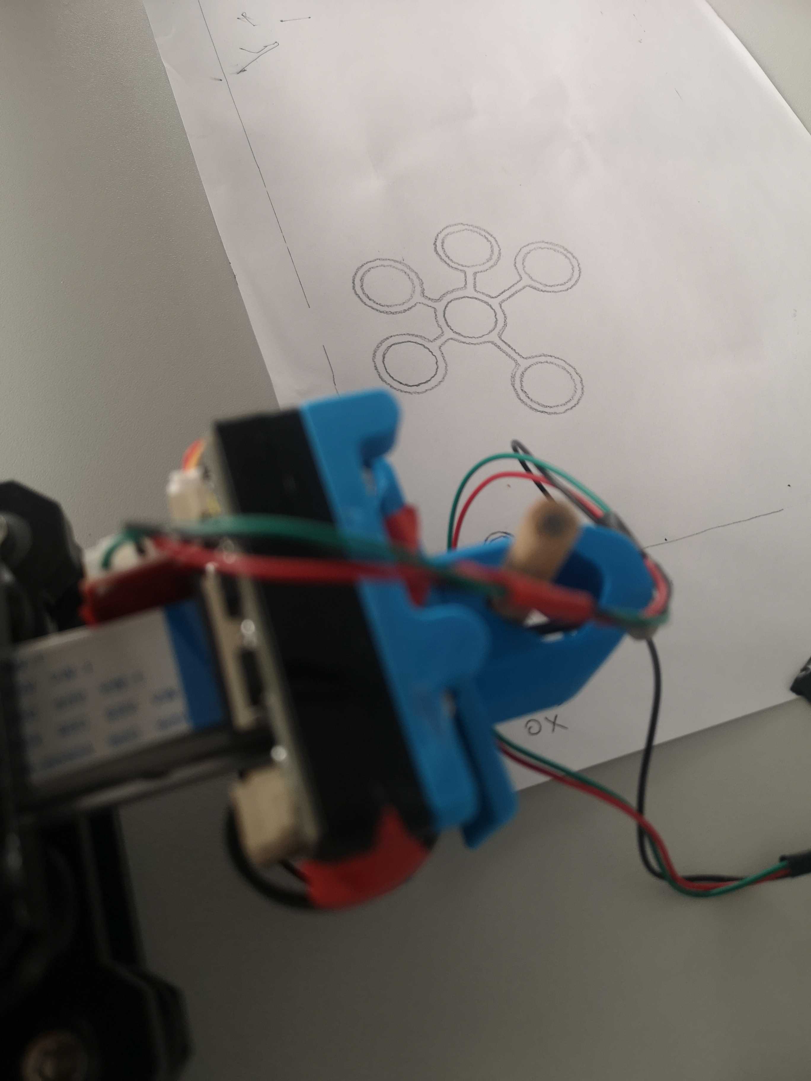
I only had time for a single shot. I was satisfied by the soothing movement of the plotter as it worked. I was so mesmerized that some of my colleagues came to see why I was thinking so hard.
It is visible in the image that there was one error in the generation where the pen wasn’t elevated properly, leaving an unwanted line. I also miscalculated the canvas size in the rush. I didn’t consider the margins properly, so the drawing extends beyond the paper edges. Funny thing is I had to stand there and elevate the pen whenever it went off bounds, otherwise the whole board would’ve been reorganized by a careless robot.

Plotted result upside down
In hindsight, I could have chosen a more recognizable shape for the demo, like a tattoo design or something iconic like a teapot.

Teapot I generated last year
What I Learned
What Worked Well
- The CoreXY mechanics configuration was straightforward once I understood the dual Y-motor setup
- Having the pen lift functionality working from yesterday saved crucial time
- My Python image enhancement algorithms produced pleasing results for generative art
- The plotter movement itself was smooth and satisfying to watch
- Implementing software features after the hardware worked helped me stay productive and energized
- Documenting the working GCode commands will save time in future sessions (hopefully)
Room for Improvement
- Design or print proper cases for the endstop modules to prevent short circuits
- Plan cable management better to allow flexible board placement, use cable coats and make it elevate from the working area
- Set canvas margins properly in the code
Closing Words
After months of preparation and a failed attempt at the previous hackathon, I finally got my plotter to create art. Sure, there were issues with pen elevation and canvas sizing, but seeing that circular pattern emerge on paper made all the troubleshooting worthwhile.
The day was a combination of hardware debugging in the morning and software feature development in the afternoon. Once the breakthrough happened around half time, I was able to add significant features to my application. Not bad for a single day’s work.

Working on the plotter setup
Happy plotting!